815 Results
View results:
Sort by:
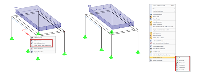
In addition to the options of Project Navigator - Display, you can modify the visibility of structures (members, surfaces, and so on) and guide objects (dimensions, comments, guidelines, and so on) in the menu and toolbar using the shortcut menus.
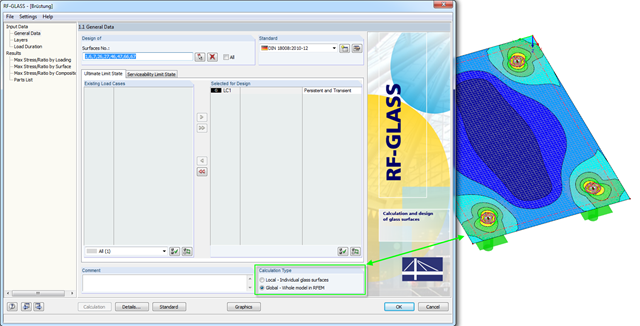
In RF-GLASS, two different calculation types are generally available in Window 1.1. There are the "Local" and the "Global" calculations.

Using the Timber Design add-on, timber column design is possible according to the 2018 NDS standard ASD method. Accurately calculating timber member compressive capacity and adjustment factors is important for safety considerations and design. The following article will verify the maximum critical buckling strength calculated by the Timber Design add-on using step-by-step analytical equations as per the NDS 2018 standard including the compressive adjustment factors, adjusted compressive design value, and final design ratio.
.png?mw=640&hash=44d3f64925841d58547bef5a5e8ff90fab8aceaf)
The American Wood Council (AWC) has released the 2018 Edition of the National Design Specification (NDS) for Wood Construction. This is the second edition of the NDS to contain a chapter dedicated to cross-laminated timber (CLT) design. Therefore, a couple of revisions were included in the 2018 NDS when compared to the previous 2015 Edition.

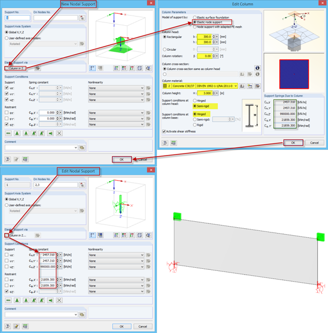
In the RF-GLASS add-on module, 3D rendering is implemented to facilitate the definition of the support conditions. This interactive graphical visualization facilitates the input and control of line and nodal supports. However, the schematic display can also be selected, if necessary.

The new generation of RFEM software is an intuitive, powerful, and easy-to-handle 3D FEA program that meets all the latest demands in modeling, calculation, and structural design. The modern design concept, as well as the introduction of new features, make the program even more innovative and user-friendly. The main differences between RFEM 6 and its previous version, RFEM 5, are discussed in the following text.

One of the innovations in RFEM 6 is the approach to designing steel connections. In contrast to RFEM 5, where the design of steel joints is based on an analytical solution, the Steel Joints add-on in RFEM 6 offers an FE solution for steel connections.

A new capability within RFEM 6 when designing concrete columns is being able to generate the moment interaction diagram according to the ACI 318-19 [1]. When designing reinforced concrete members, the moment interaction diagram is an essential tool. The moment interaction diagram represents the relationship between the bending moment and axial force at any given point along a reinforced member. Valuable information is shown visually like strength and how the concrete behaves under different loading conditions.

Silos are used as large containers for storage of bulk materials such as agricultural products or source materials as well as intermediates of industrial production. The structural engineering of such structures requires a precise knowledge of the stresses due to particulate solids in the building structure. The standard EN 1991‑4 "Actions on Silos and Tanks" [1] provides the general principles and requirements for determining these actions.
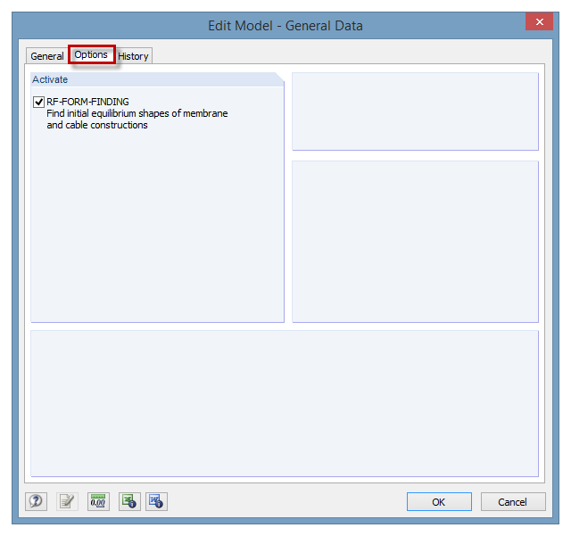
The RF‑FORM‑FINDING add‑on module can be activated in the "Edit Model - General Data" window, "Options" tab. By activating the module, a new RF‑FORM‑FINDING load case is created and an additional menu appears in the main program, allowing for the definition of prestress conditions for membrane and cable elements.
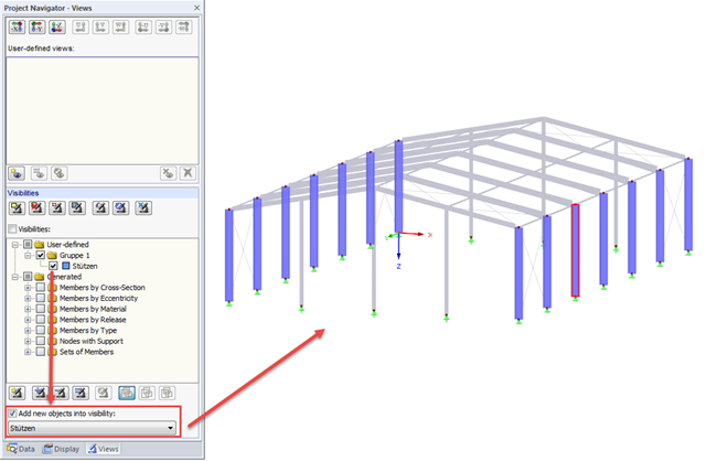
If new objects are created in an existing visibility, they are hidden immediately, since they do not comply with the particular visibility. However, if you want to display the new objects immediately in an existing visibility, for example when creating a new member, simply select the "Add new objects to visibility" check box.

For line supports, there is an option to graphically display the additional information for all directions.

In RF‑/FOUNDATION Pro, the available reinforcing steel diameters can be adjusted by the user. The adjustment of the available rebar diameters works similarly to the same function in the RF‑/CONCRETE (Members) and RF‑/CONCRETE Columns add‑on modules.
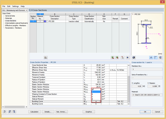
You can adjust the buckling curve of a cross-section in RF-/STEEL EC3, if necessary. This can be done in Window 1.3, Cross‑Sections.
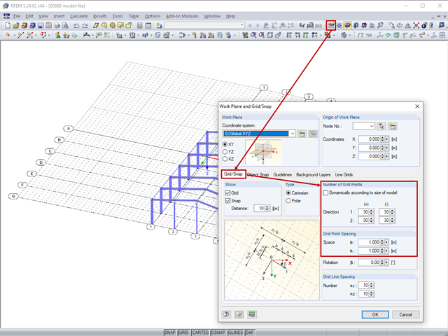
The length of the guidelines corresponds to the dimensions of the set grid and can be adapted by setting the grid.

It is possible to edit a reinforcement layout or an existing reinforcement directly in the reinforcement's 3D rendering.

In RF‑/FOUNDATION Pro, reinforcement drawings are displayed after designing the foundation, where you can record all necessary structures of the reinforcement steel.

For relatively large or relatively small surfaces, it can happen that the automatically created result values do not fit the model: In the case of large surfaces, there can be too many result values; in the case of small surfaces, too few.
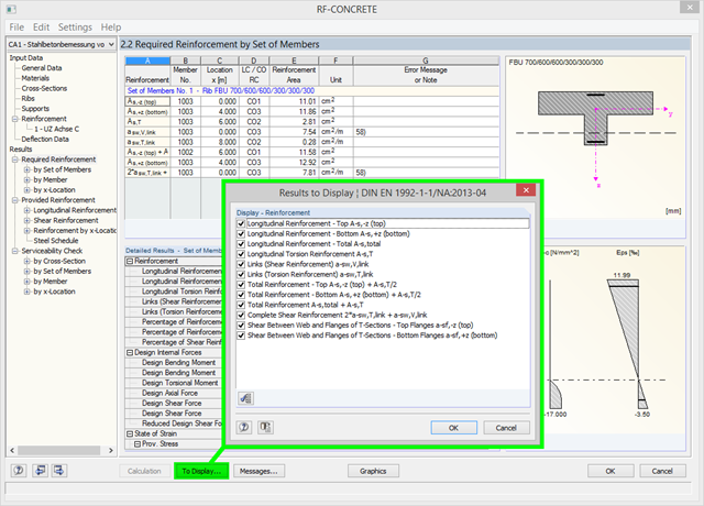
Using the [To Display…] button, you can specify the amount of reinforcement to be displayed in the results of the required reinforcement in Window 2.2 of RF‑CONCRETE and CONCRETE. In addition to the default setting, you can display the resulting reinforcement amount as (for example) the sum of the longitudinal and longitudinal torsion reinforcement, or the sum of the torsion and shear reinforcement. You can also reduce the number of preset results, of course.